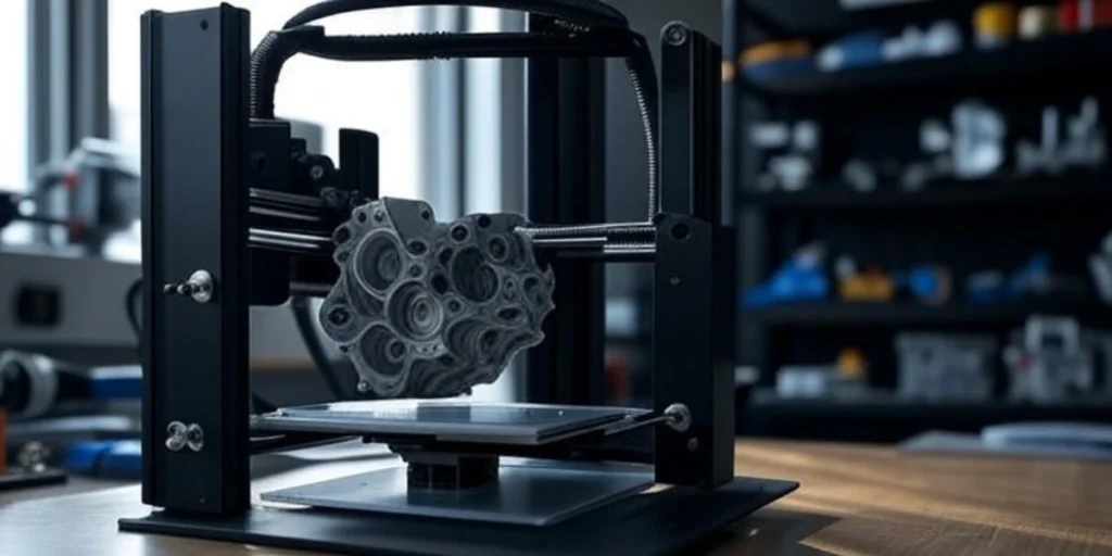
Introduction to 3D Printing in Mechanical Design
3D printing—also known as additive manufacturing—has transformed the way mechanical components are designed and produced. From rapid prototyping to functional part production, its integration with Mechanical CAD (Computer-Aided Design) has become essential for modern product development.
Mechanical engineers today don’t just rely on static models; they incorporate motion simulation and kinematics into their CAD workflows to optimize designs. The CAD–CAM–3D printing pipeline enables designers to simulate how parts move, interact, and assemble—before a single part is printed.
What is Mechanical CAD Design?
Mechanical CAD design involves creating digital representations of physical mechanical components using specialized software. Key features include:
- Parametric modeling for design flexibility.
- Solid modeling for prototyping.
- Surface modeling for complex shapes and aesthetics.
Common software includes SolidWorks, CATIA, and Fusion 360. These tools help mechanical engineers simulate motion, evaluate stress, and prepare models for 3D printing service.

How 3D Printing Works: A Quick Recap
Unlike traditional subtractive methods, 3D printing builds components layer by layer. Major types include:
- FDM (Fused Deposition Modeling) – great for prototypes.
- SLA (Stereolithography) – high detail, resin-based.
- SLS (Selective Laser Sintering) – uses powders for strong parts.
- DMLS (Direct Metal Laser Sintering) – metal part manufacturing.
Materials include PLA, ABS, nylon, resin, and metal powders. Ideal for both mechanical prototyping and end-use production.
The Role of CAD in 3D Printing
CAD modeling is the first and most critical step before 3D printing. Engineers design models and export them in formats like:
- STL – most common for slicing software.
- STEP – for parametric and assembly data.
- IGES – supports surface geometry and legacy systems.
Post-processing involves slicing the file and generating G-code for the printer.
Types of CAD Modeling for 3D Printing
Understanding different modeling methods is essential:
- Solid modeling – ideal for functional prototypes.
- Surface modeling – for curvy, aesthetic parts.
- Parametric modeling – allows easy design changes.
- Direct modeling – useful for quick edits.
- Code-driven CAD – like OpenSCAD, for programmatic design.
These models guide how parts behave in simulations and how they are interpreted by CAD 3D printing tools.
Top CAD Software Used in 3D Printing
Here are the top software choices for mechanical CAD integrated with 3D printing near me:
- Fusion 360 – cloud-based with strong simulation tools.
- SolidWorks – industry standard for mechanical assemblies.
- CATIA – used for complex surface and aerospace components.
- Tinkercad – beginner-friendly.
These platforms support motion simulation and export to 3D printable formats.
Benefits of Integrating CAD with 3D Printing
- Rapid prototyping and iteration.
- Motion analysis before physical testing.
- Mass customization with digital twins.
- Material and cost optimization.
- Kinematic simulation ensures mechanisms move as intended.
Simulating real-world mechanics saves time and helps deliver reliable products.
Why Motion Simulation and Kinematics Matter in Mechanical CAD
When designing complex mechanical systems, it’s not enough to just model parts—you need to simulate how they move. Here’s how:
a. Mechanism Design
Engineers use CAD to create mechanical linkages, cams, sliders, and gear systems. Motion simulation ensures:
- Correct degrees of freedom.
- Proper range of motion.
- Collision avoidance.
b. Assembly Constraints
Using mates and constraints (e.g., concentric, coincident, gear mates), CAD software defines real-world part interactions.
- Ensures correct alignment and fit.
- Prevents over-constraining or under-defining assemblies.
c. Motion Analysis
By applying forces, torques, and motion drivers, engineers:
- Visualize movement.
- Analyze velocity, acceleration, and joint reactions.
- Optimize designs before production or CAD 3D printing.
Motion simulation reduces trial and error, cuts prototyping costs, and improves performance.
Challenges in CAD–3D Printing Integration
- STL files may cause mesh errors.
- Poor tolerance modeling can affect fit.
- Software-hardware compatibility issues.
- Material limits under dynamic loading.
Understanding motion helps in avoiding these pitfalls before printing.
Future Trends: CAD and 3D Printing in Smart Manufacturing
- AI-generated designs using kinematic constraints.
- Cloud-based CAD for global collaboration.
- Digital twins for testing and lifecycle simulation.
- Industry 4.0 integration with IoT, sensors, and additive workflows.
These trends highlight why mastering CAD and motion simulation is essential for modern engineers.
Conclusion: Designing the Future with CAD and 3D Printing
Incorporating motion simulation and kinematics in CAD empowers mechanical engineers to build smarter, more reliable systems. From mechanism analysis to 3D printing-ready models, motion-aware CAD modeling is the future.
Whether you’re designing a robotic arm or an automotive linkage, integrating motion into your CAD workflow saves time, cuts cost, and improves quality.
CADify Studio can help manufacturing companies bridge the gap between CAD design, simulation, and real-world production with expertise in 3D printing, motion analysis, and mechanical design.
Contact Details
Email: cadifystudio@gmail.com
Phone: +91 880-281-0306

